3D CG is a technology for creating realistic images using computers.
In addition to still images, it is used in many fields such as commercials, animations, and movies (including compositing with live action).
To create a 3D CG image, we need many processes such as creating the shape of objects (modeling), adjusting the texture (shading), and controlling the lights and viewpoint (lighting).
In order to create a moving image, motion design and camera work are also required.
Furthermore, a lot of computational time is required to create many frames.
Since 3D CG is computationally heavy, an expensive computer had been used in late 20th century.
Now personal computers are commonly used for 3D CG, though high spec computers are preferred.
* Here the word 3D does not mean stereoscopic technology, which is used for 3D films (stereo films) and 3D television.
Modeling — coordinate system
In modeling, knowledge about three-dimensional coordinates is required, since objects, lights, and a camera are arranged on coordinates.
However, the coordinate system differs slightly depending on the software.
Right-handed system and left-handed system
When the x-axis is assigned to the thumb, the y-axis to the index finger, and the z-axis to the middle finger, the coordinate system with the right-hand arrangement is called the right-handed system, and the one with the left-hand arrangement the left-handed system.
In mathematics, the right-handed system is commonly used, but in 3D CG the coordinate system depends on the software (it seems that most use right-handed system), so you need to be careful which one is used.
As shown in the figure, in the right-handed system the z direction means the near side, and in the left-handed system the z direction corresponds to the far side.
y-up and z-up
y-up is the coordinate system with assigning the y-axis up, and z-up is the one with assigning the z-axis up.
In 3D CG, it is common to take x on the right on the screen and y on the top, so y-up system is used.
Therefore, in the right-handed system the z-axis is on the near side, and in a left-handed system the z-axis is on the far side.
On the other hand, CAD (drafting software) usually uses a plan (top view) as the xy plane, so z-up system is often used.
In mathematics the right-handed z-up system is used.
By the way, in main 3D CG software, Maya, Houdini, Shade use the right-handed y-up system, LightWave uses the left-handed y-up system, and Rhinoceros uses the right-handed z-up system.
Unit
In 3D CG, the shape of an object is represented by coordinates (x, y, z).
Coordinates are treated as simple numerical values having no units, but software assumes the default unit: mm, cm, or m.
When dealing with physical phenomena such as free fall due to gravity in animation, the unit is very important because it determines the speed of phenomena.
Direction of rotation
When rotating an object, the axis of rotation and the angle must be specified.
In general, the angle is measured in the cyclic order: x to y, y to z, or z to x.
That is, for rotation around the x-axis, the direction from y to z is positive, and so on.
Object coordinates, world coordinates, screen coordinates
When modeling an object, first create an object, rotate and translate it, and place it.
The coordinates used to create the object are called object coordinates.
The coordinates on which objects, light sources, and the camera are placed are called world coordinates.
When this is viewed from the camera, a perspective view can be calculated.
In this way a rendered image is obtained, and the coordinates on the image plain are screen coordinates.
Modeling — surface model and solid model
Roughly speaking, there are two types of models to describe a 3D object.
(1) Surface model
A model with only a surface, made up of a collection of polygons.
Mainly used in the Z-buffer algorithm or in the scanline algorithm.
The following methods are used for modeling an object.
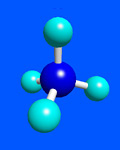
Primitive
Making an object by combining basic shapes (made of polygons) such as spheres, ellipsoids, cones, cylinders and planes.
Revolution
Drawing the cross section and revolving it around an axis.
Extrusion
Drawing the cross section and extruding it vertically or sweeping it along a curve.
Curved surface
Modeling a curved smooth surface using Bézier curves or NURBS (Non-Uniform Rational B-Splines).
(2) Solid model
As opposed to a surface model with only s surface, a solid model is filled with a content.
This model is mainly used for ray tracing.
Solid model can be represented as a polygon mesh with geometric information (B-reps, boundary representation), or discribed by equations.
B-reps
A polygon mesh model having information on the direction of the surface is a solid model because the inside and outside of the model can be distinguished by software.
(Note) The appearance of B-reps model is a polygon mesh, but it can discribe refraction as a solid model.
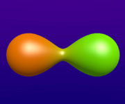
Primitive
Basic shapes described by equations, curved surfaces, and a "metaball" (made of density spheres) can be used depending on the software.
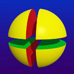
Boolean
Set operation (Boolean operation, Boolean) of solid models can be used in modeling.
The operation is sometimes called CSG (constructive solid geometry).
If solids are A and B, the union A+B (A∪B) can be created with any software, but some software can also describe solids such as A×B (A∩B) and A−B.
In the actual modeling, many methods described above are used to make an object, as well as scaling, rotation, and translation of the object to arrangement it.
Sometimes, several objects are appropriately grouped (for example, fingers and palms are grouped as a hand) to make modeling easier.
Revolution (wireframe)
Primitives made of polygon mesh
Example of a metaball
Example of Boolean: a sphere−rectangulars
Among shape data, DXF and STL are general-purpose file formats for storing shapes represented by polygons.
Each is a set of coordinate values and normal line (surface direction) information of each polygon.
DXF (Drawing Exchange Format) is a general-purpose 2D / 3D data storage format used by AutoDesk, and is used in CAD applications.
STL (STereo Lithography) expresses a shape by a triangular surface element and is often used as a data format for 3D printers.