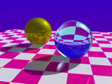
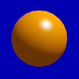
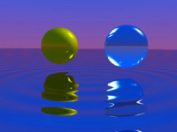
Examples of ray tracing
This is a simple method of removing hidden surfaces by painting polygons in order from the far side to the near side.
Sometimes used for rendering in CAD software.
Shadows and transparent objects cannot be handled.
Anti-aliasing is not possible.
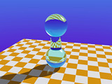
Examples of ray tracing
 |
 |
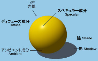
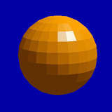
| Flat shading | Smooth shading (Phong) |
 |
 |
 |
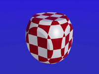
| Texture mapping |
Reflection mapping (environment mapping) |
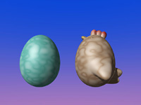
Bump mapping (rough skin) |
 |
 |
 |
| Bump mapping (wave) | Solid texture | Solid texture |
 |
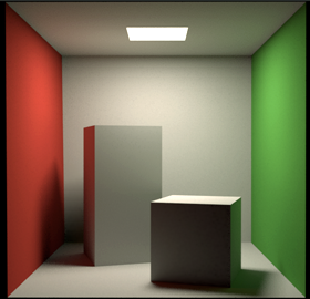 |
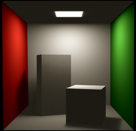
| Ray tracing with a local illumination model |
Ray tracing with a global illumination model |