 |
 |
 |
| Fig. A-1: Example of translational motion: linear motion with constant acceleration to the right | Fig. A-2: Example of translational motion: free fall | Fig. A-3: Example of translational motion: translational circular motion |
Tidal force is an old problem that was solved in Newton's time. To obtain the tidal force, we only need to calculate the difference between the gravity from the celestial body at each point on the earth and the gravity at the center of the earth. However, the interpretation of tidal force seems to be a different matter. For example, a search of the web reveals many public and private sites that explain tidal force with wrong interpretations. In particular, most of them incorrectly refer to translational inertial force as centrifugal force, causing confusion. The same is true for earth science textbooks.
This may be due to the confusion of the following concepts:
In fact, many articles (even in earth science textbooks) refer to translational circular motion as rotation. This is a misuse of the word "rotation." They also call translational inertial force "centrifugal force equal everywhere." This is a misuse of "centrifugal force" that comes from misunderstanding of the definition of centrifugal force. The correct understanding of rigid body motion and inertial forces is essential for understanding the tidal force, so let us summarize them below.
In contrast to a "point mass" whose size is negligible, a non-deforming object with size is called a "rigid body." The motion of a rigid body can be expressed as a composite of two motions. One is translational motion, in which the object moves without changing its orientation, and the other is rotational motion, in which the object rotates around a rotational axis. The fact that there are translational and rotational motions of a rigid body is taught even in high school physics. Unfortunately, the course ends with only statics (equilibrium, moment of force). However, if you have knowledge of accelerated motion, it will not be difficult to understand the dynamics of a rigid body.
1. Translational motion
Motion in which a rigid body moves while maintaining its orientation with respect to the inertial frame of reference.
If a camera is fixed to a rigid body in translational motion and a starry sky is photographed, the stars will stand still.
If the rigid body does not change its orientation during the motion, it is translational motion even if it is not constant velocity motion or linear motion.
Motion along a circle, as shown in Fig. A-3, is also translational motion.
In the coordinate system on a rigid body in translational motion, centrifugal force never appears.
|
|
|
| Fig. A-1: Example of translational motion: linear motion with constant acceleration to the right | Fig. A-2: Example of translational motion: free fall | Fig. A-3: Example of translational motion: translational circular motion |
2. Rotational motion
Motion in which a rigid body rotates about an axis and changes its orientation with respect to the inertial frame.
When a camera is fixed to a rigid body in rotational motion and a starry sky is photographed, stars will flow.
The position of the axis of rotation can be chosen freely (it does not have to be at the center of mass).
If another position is chosen for the axis of rotation, the difference of motion due to the difference of the axis of rotation becomes translational motion.
In a coordinate system on a rigid body in rotational motion, centrifugal force always appears.
 |
 |
| Fig. A-4: Example of rotational motion. | Fig. A-5: Example of rotational motion - this motion can be decomposed into rotational motion in Fig. A-4 and translational motion in Fig. A-3 |
In general, in a non-inertial frame, i.e. a coordinate system with accelerated motion, a fictious force due to the inertia of the mass, i.e. inertial force, appears. Depending on the type of accelerated motion, the inertial force appearing in the coordinate system differs.
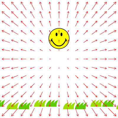
1. Translational accelerated frame
When a rigid body is in translational accelerated motion as shown in Figures A-1 through A-3, a uniform (equal everywhere) inertial force in the opposite direction to the acceleration of the rigid body appears in the coordinate system of the rigid body.
The uniform inertial force is also called "translational inertial force."
The inertial force is equal everywhere because in translational motion each point of a rigid body has the same motion.
Let \( {\boldsymbol{W}} \)
be the acceleration of the coordinate system and
\( {\boldsymbol{F'}} \) be the inertial force,
then the inertial force acting on the mass \( m \)
is given by
Here, \( {\boldsymbol{W}} \) is a constant vector independent of position. The inertial force fields seen from the reference frame of the rigid body are represented graphically in Figures A-6 through A-8.
 |
 |
 |
| Fig. A-6. Inertial force due to the translationl motion with constant acceleration to the right (Fig. A-1). | Fig. A-7. Inertial force due to the free fall (Fig. A-2). | Fig. A-8. Inertial force due to the translational circular motion (Fig. A-3) |
In the case of translational motion with constant acceleration as in Figures A-1 and A-2, the direction of the inertial force does not change. For example, in the accelerated frame of Fig. A-1, leftward inertial force appears as shown in Fig. A-6. In the accelerated frame of Fig. A-2, inertial force is upward as shown in Fig. A-7. However, for translational motion along a circle as in Fig. A-3, the inertial force appearing in the frame of the rigid body changes its direction with the motion as shown in Fig. A-8. In this case, the acceleration is a function of time: \( {\boldsymbol{W}} = {\boldsymbol{W}}(t) \).
2. Rotating frame
Consider inertial forces appearing in a coordinate system fixed to a rigid body in rotation.
Let \( {\boldsymbol{r}} \) be the distance from the origin on the axis of rotation and
\( {\boldsymbol{\omega }} \) be the angular velocity vector,
then the following inertial force \( {\boldsymbol{F'}} \) appears in the rotating frame.
In the equation, the dot above the variable indicates the time derivative.
The terms on the right-hand side are called (1) centrifugal force, (2) Coriolis force, and (3) Euler force, in that order. The Coriolis force appears only when the point mass has a velocity relative to the rotating frame. The Euler force appears only when the angular velocity changes with time. Among these inertial forces that appear in a rotating frame, only the centrifugal force can be expressed as a function of position (as a so-called potential force). Coriolis force and Euler force cannot be expressed in terms of potential because they involve velocity (\( {\boldsymbol{\dot r}} \) in the above equation) or rate of change in angular velocity (\( {\boldsymbol{\dot \omega }} \) in the above equation) .
(1) Centrifugal force
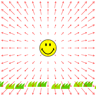
Centrifugal force is a force acting perpendicular to the axis of rotation and outward from the axis, and its magnitude is proportional to the distance from the axis.
The centrifugal force fields seen from the reference frame of the rotating rigid body are shown in Figures A-9 and A-10.
If \( {\boldsymbol{r}}_ \bot \) is the component of
\( {\boldsymbol{r}} \) perpendicular to the axis of rotation,
the centrifugal force can be expressed by the following simple equation.
This is the same as the formula for centrifugal force \( mr{\omega ^2} \) taught in high schools.
 |
 |
| Fig. A-9. Centrifugal force appearing in a rotating frame (Fig. A-4), where the rotational axis is at the center of a rigid body. | Fig. A-10. Centrifugal force appearing in a rotating frame (Fig. A-5), where the rotational axis is not at the center of a rigid body. |
 |
| Fig. A-11. Rotating reference frame. The angular velocity vector is defined as the vector in the direction of the axis of rotation. |
(2) Coriolis force
Force acting on a point mass in motion relative to the rotating frame.
Since it does not act on a point mass at rest relative to the rotating frame, we do not need to consider the Coriolis force unless the point mass is in motion.
(3) Euler force
Force that appears when the angular velocity vector changes.
In contrast to the centrifugal force, which acts in the radial direction, the Euler force acts in a direction perpendicular to the radius and is therefore sometimes called the transverse inertial force.
When the angular velocity is constant, the Euler force need not be considered.
Since a point mass has no size, it is meaningless to consider translational motion where orientation matters. Therefore, when considering a point mass moving in a circle, we usually get on a rotating frame that rotates with the point mass. In this case, the inertial force acting on the mass point is the centrifugal force proportional to the distance from the center of rotation.
However, as mentioned here, for a rigid body like the earth, which has a certain size, we must distinguish between circular motion (translational motion along a circle) and rotational motion (motion of changing orientation). In other words, it is necessary to distinguish whether the coordinate system fixed to the rigid body is a translational accelerated frame or a rotating frame. If it is a translational accelerated frame, the inertial force is uniform and centrifugal force will never appear. On the other hand, if it is a rotating frame, centrifugal force always appears.
The reason why many people mistake the translational inertial force associated with revolution for centrifugal force may be because they divide the translational circular motion of the earth into individual points and misunderstand the circular motion of each point as rotational motion, just like the circular motion of a point mass (see Figures A-12 and A-13). Such people say that each point of the earth has a circular motion with the same radius and a different center, but it just means that the earth is in a translational circular motion. It does not mean that each point is rotating together with each individual rotational coordinate system. Therefore, it is wrong to consider the circular motion of each point as rotational motion. Of course, the inertial force appearing at each point is not centrifugal force. In fact, in translational accelerated motion, all points have the same motion, so uniform inertial force appears as in equation (1) (If \( {\boldsymbol{W}} \) is the earth's acceleration, equation \( {\boldsymbol{F'}} = - m{\boldsymbol{W}} \) gives the uniform inertial force).
 |
|
| Fig. A-12: Misleading illustration. If the motion of the earth is divided into circular motion of each point, the circular motion may be mistaken for rotational motion. It is also better not to draw the center or radius of each circle because each point is not rotating around each center (but just in the translational motion as a point on the rigid body). | Fig. A-13: In order to show that the earth's motion is a translational motion along a circle, an illustration like this one (with an object indicating the orientation on the earth) would be better. |
Whether the coordinate system we are on is rotating or not can be easily understood by considering whether the distant landscape is flowing or not (see CG videos Fig. A-14b and Fig. A-15b, for reference). In addition, whether the inertial force appearing in the coordinate system is translational inertial force or centrifugal force can be determined by looking at the equation. That is, the potential of translational inertial force is a linear function of radius, and the force itself is constant. On the other hand, the potential of centrifugal force is a quadratic function of radius, and the force itself is a linear function. Alternatively, the difference will be obvious if the force field is represented graphically as shown in Figures A-6 through A-10.
| Fig. A-14a. A camera in translational circular motion around a small stationary sphere. | Fig. A-14b. View from a camera in translational circular motion around a small stationary sphere. This motion should not be called rotation. In the reference frame of this camera, inertial forces as in Fig. A-8 appear. |
 |
 |
| Fig. A-15a. A camera in rotational motion around a small stationary sphere. | Fig. A-15b.
View from a camera in rotational motion around a small stationary sphere.
The camera rotates with the same period as its circular motion (revolution).
In the rotating reference frame, centrifugal forces as in Fig. A-10 appear. For the landscape, the image included in the planetarium software "Stellarium" is used. |
Reference
Since the motion of a rigid body is a combination of translational and rotational motions, inertial forces due to both translational motion and rotational motion may appear in a non-inertial reference frame on a rigid body. In Landau-Lifshitz's textbook, the equation of motion for a non-inertial frame is written as follows [Eq. (29.7) of the Shorter course, and Eq. (39.7) of the Course]:\[ m{\frac{{\text{d}{\boldsymbol{v}}}}{{\text{d}t}}} = - \frac{{\partial U}}{{\partial {\boldsymbol{r}}}} - m{\boldsymbol{W}} + m{\boldsymbol{r}} \times \mathit{\boldsymbol{\dot \Omega }} + 2m{\boldsymbol{v}} \times \mathit{\boldsymbol{\Omega }} + m\mathit{\boldsymbol{\Omega }} \times ({\boldsymbol{r}} \times \boldsymbol{\mathit{\Omega }}). \]* In this equation, \( {\mathit{\boldsymbol{\Omega}}} \) corresponds to \( {\boldsymbol{\omega}} \), and \( {\boldsymbol{v}} \) corresponds to \( {\boldsymbol{\dot r}} \) in this article, respectively.
The meaning of each term on the right-hand side is as follows:
· 1st term … potential force (e.g., gravity),
· 2nd term … uniform inertial force due to translational accelerated motion (called uniform force field in the textbook),
· 3rd term … Euler force due to rotational motion,
· 4th term … Coriolis force due to rotational motion,
· 5th term … centrifugal force due to rotational motion.